Symmetrical and asymmetrical interferences
Symmetrical and asymmetrical interferences are the main challenges in the field of electromagnetic compatibility (EMC). Understanding these two types of interference is crucial for recognizing interference in electrical systems and taking suitable measures to reduce it. Both types of interference differ fundamentally in their origin, their mode of spreading and their effects on electronic devices and systems.
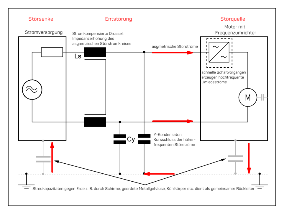
Asymmetrical interferences, also known as common mode interferences, occur when the same interference voltage with identical polarity spreads in both conductors of a line pair. This means that the interference flows in both conductors at the same time and in the same direction. A typical source of asymmetrical interference is external and internal electromagnetic field, which couple into the network capacitively and inductively, but also via radiation. For example, frequency converters that aer not sufficiently interference suppressed can generate such fields, which are transmitted to other devices as common mode interference via the power supply. As the interference affects both conductors in the same way, it can spread over large areas and affect several devices simultaneously. Another characteristic feature of common mode interference is that it is often coupled in via housings and earth connections and can lead to malfunctions in sensitive devices.
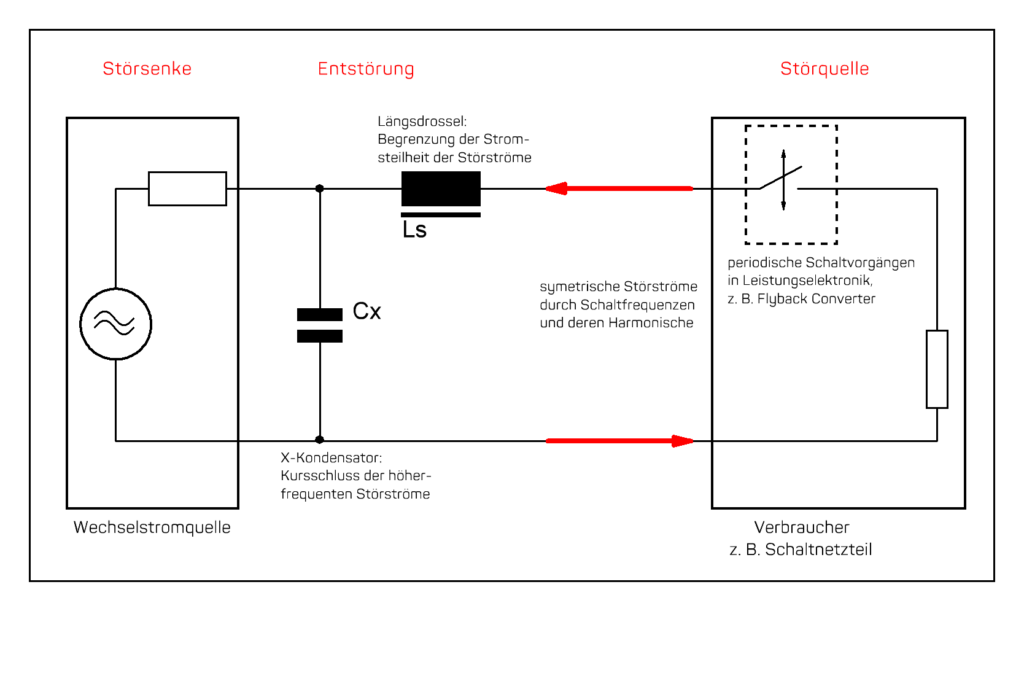
In contrast, symmetrical interferences, also known as push-pull interferences, are caused by voltage differences between the conductors of a pair of lines. This interference acts as a differential voltage, with the interference current flowing in opposite directions in the two conductors. Symmetrical interference typically occurs within a system and is often the result of unbalanced conductor routing, switching operations by the power electronics or ground potential shifts. A classic example of symmetrical interferences are interferences caused by switching processes in transformers or stray fields in electrical circuits. This type of interference primarily affects signal quality, as it leads to distortion or data errors in communication systems. In the high-frequency range, symmetrical interferences can also cause unwanted feedback, which impairs the functionality of sensitive circuits.
The causes of these two types of interference are varied and range from external electromagnetic influences to internal system-related processes. Both types of interference can have a significant impact on the function of electrical systems. Asymmetrical interferences cause devices to restart unexpectedly, signals to be disturbed or distorted and safety-critical functions to fail. Symmetrical interferences particularly affect the quality of signal transmission and cause data errors in communication systems, interferences in the high-frequency range and unwanted feedback in circuits.
Suitable measurement methods must be used to detect and analyze interferences. The common mode measurement checks whether a similar interference occurs on both conductors, while the differential mode measurement checks whether there is a voltage difference between the conductors. Spectrum analyzers and oscilloscopes are primarily used for measurement. Measurement is essential in order to correctly determine the type of interference and take appropriate countermeasures.
Measures against asymmetrical interferences include the use of common-mode chokes, shielding against external electromagnetic fields and improving the earthing concept. Common-mode chokes reduce asymmetrical interference signals by increasing the impedance of the current path and thus attenuating the current in both conductors equally in the required frequency range. Shields prevent external electromagnetic fields from entering the system and careful earthing ensures that no unwanted interference currents can flow through the device housing. In order to minimize interference on the protective earth conductor beyond that, protective earth chokes are used.
Differential clock filters, which are specially designed to reduce voltage differences between the forward and return conductors, are particularly helpful against symmetrical interferences. It is also important to optimize the conductor routing in order to avoid symmetrical interference from the outset. Reducing stray fields, for example by using suitable components such as shielded transformers, can also help to minimize symmetrical interference.
In practice, both types of interference often occur simultaneously. One example of this is a switched-mode power supply. Asymmetrical interferences can be caused by electromagnetic fields that radiate from the power supply housing and interfere with surrounding components. At the same time, symmetrical interference can be generated by internal switching processes that cause voltage differences between the conductors and reduce the signal quality. The combined use of common mode chokes, filters and optimized conductor routing can effectively reduce such interferences and improve the electromagnetic compatibility of the system.
Distinguishing between symmetrical and asymmetrical interferences is an essential part of EMC analysis and optimization. Only by specifically identifying the type of interference, suitable measures to prevent interferences can be implemented. The use of filters, shielding and suitable conductor structures plays a central role in ensuring electromagnetic compatibility and guarantees stable and interference-free systems in the long term.