
An exceeded limit is a starting point.
Which frequencies are affected? Are the emissions conducted through cables or radiated? The test report and operating conditions guide the next step.
BKT helps clarify the requirements for the filter solution.
The device is developed. The deadline is set. But EMC testing reveals a problem. Together, we establish how a suitable interference suppression solution can move your product forward.
Talk directly to the filter manufacturer in Prenzlau.
Start by reviewing the test report, identifying the cause and evaluating an appropriate change. A correctly designed EMI filter can help with conducted high-frequency interference. BKT supports filter selection, development and integration discussions. Retesting the complete device establishes whether the requirements are met.
Explore the principle. Understand the next step.
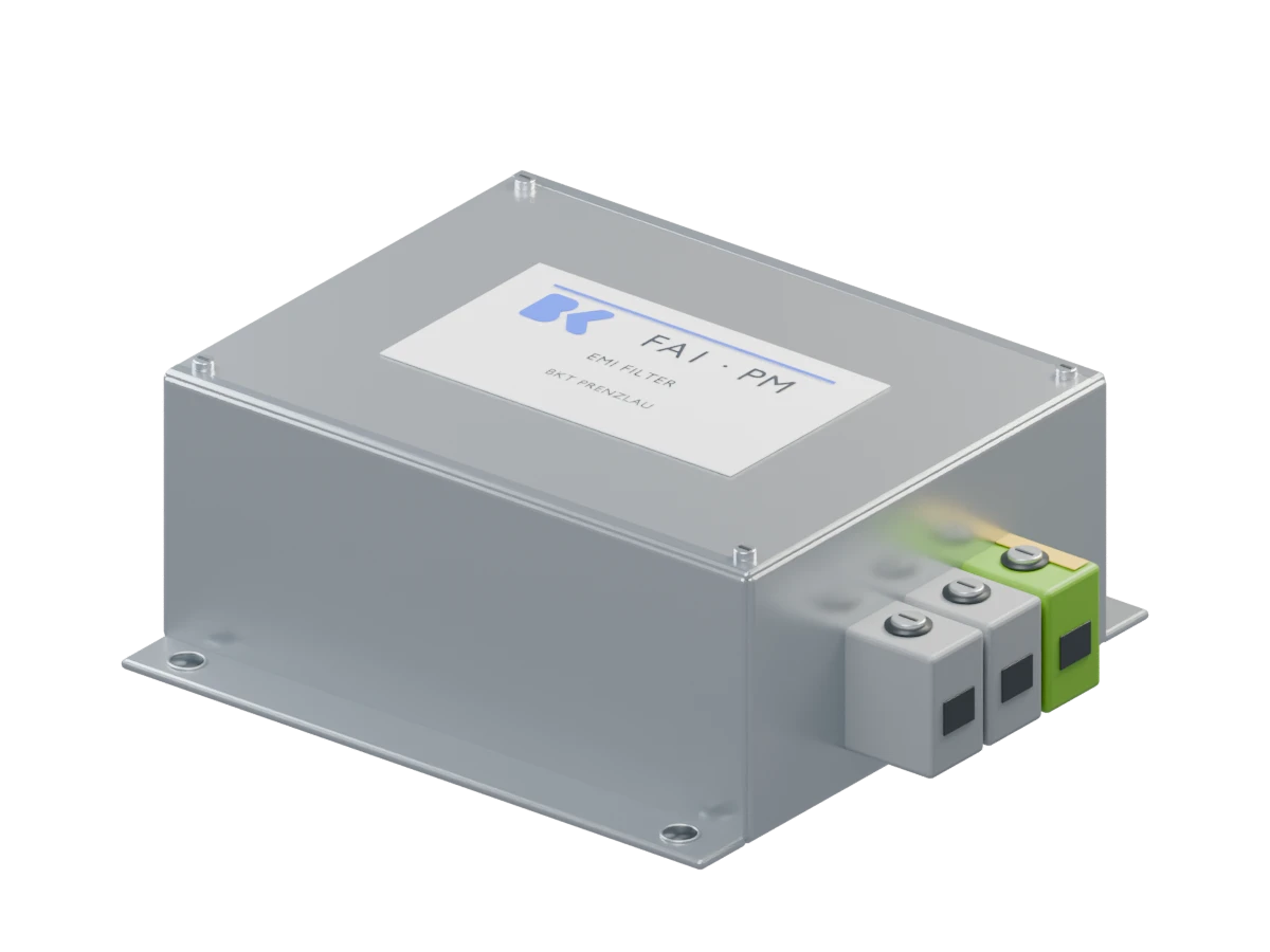 Loading the 3D view …
Which frequencies are affected? Are the emissions conducted through cables or radiated? The test report and operating conditions guide the next step.
Chokes and capacitors work together to attenuate high-frequency interference on the supply connection. The design and installation need to match the application.
The optimised complete device is measured again under the relevant test conditions. This shows whether the measure is sufficient or further changes are needed.
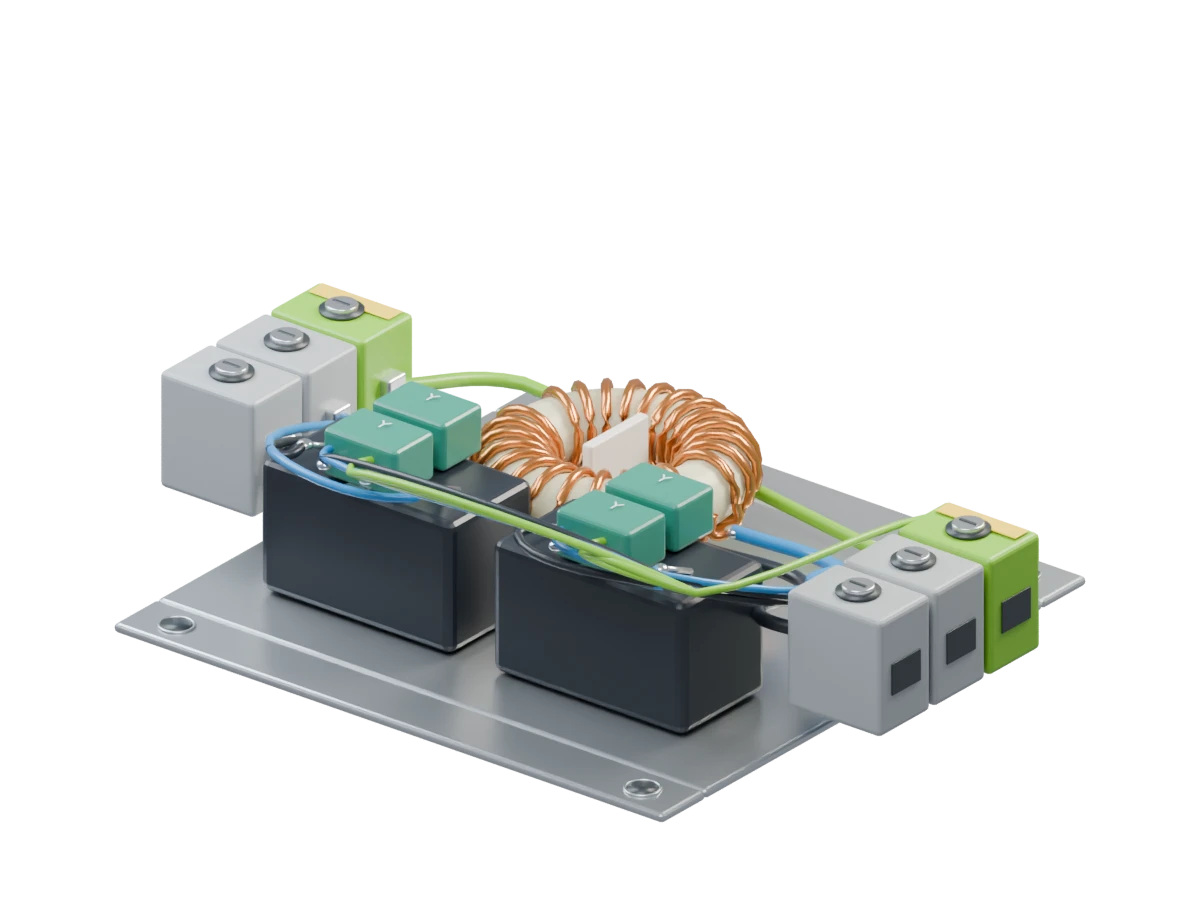
Choke. The core and windings impede high-frequency interference. Their design is matched to current, frequency range and application.
X capacitor. Connected between the active conductors, it contributes to attenuating differential-mode interference.
Y capacitors. They provide a capacitive path to the earth reference. Permissible leakage current is one of the design constraints.
Connections. Wiring, earth bonding and separation of input and output affect the installed filter’s performance.
Select a component above or directly in the model. It will light up in blue.
High-frequency components are superimposed on the supply waveform.
Choose “Explore filter action” to compare the principle.
Schematic · not a measured waveform. The effect is verified on the device.
You know your device. We know filters. Together, we create a clear path to the next measurement, with practical tasks for each side.
Which test failed? Identify the disturbance, affected frequencies, exceeded limits and the operating condition of your device. These findings determine the next step.
A defined problem instead of choosing a filter by guesswork.Provide the report, measurement plots and a brief description of the device.
Review the findings with you and establish where filtering can help.
Interference can travel along conductors or through electromagnetic fields. Filter selection also depends on voltage, current, connections, available space and leakage-current requirements.
A shared set of requirements for interference suppression.Describe the installation, cable routing and operating requirements.
Agree on the electrical and mechanical requirements and discuss measurement support where needed.
An existing series filter may be suitable. Different connections, housing constraints or filtering requirements may call for a custom solution.
A defined design to evaluate in your device.Agree on space, expected quantities and the project schedule.
Propose a series design or custom development and agree on the sample.
Performance depends on the complete device. Placement, grounding, shielding and separating unfiltered from filtered wiring can significantly affect the result.
A representative device setup for retesting.Have the sample installed correctly in the intended configuration.
Clarify connections and installation requirements and support technical questions about the filter.
Retesting shows whether the changes are sufficient. If issues remain, review the filter and installation together. The result for the complete device is what matters.
Measured evidence to support the next stage of product release.Arrange retesting with your test laboratory and share the results.
Refine the filter solution using the results and prepare the production design.
EMC covers different tests. Effective solutions consider both the source of interference and the path it takes.
Exceeded conducted voltage or current limits? Chokes and capacitors can attenuate high-frequency noise. Frequency range, interference mode and installation determine the approach.
Explore EMI filtersWhen a cable radiates interference, filtering can form part of the solution. Shielding, enclosure bonding and PCB layout may also need attention.
A reset, interruption or malfunction during testing requires focused analysis. ESD, burst, surge and other disturbances each require appropriate measures.
You do not need every answer yet. Start with what you already know; we can identify the remaining questions together.
Test standard, frequencies, exceeded limits and operating conditions.
What the device does and the environment it operates in.
Voltage, current, phases and special operating conditions.
Available space, photos, cable lengths and connection types.
For example leakage current, protection class and required approvals.
Samples, planned production quantities and the next test date.
Start with a short description. We can then arrange the relevant document exchange.
We also support projects that are still in development. Agreeing on filtering requirements, space and connections early makes integration easier. BKT brings together development, prototyping and in-house measurement capabilities in Prenzlau.
Keep the test report, measurement plots and setup details. Identify whether the issue concerns emissions or immunity and which frequencies or test conditions are involved. BKT can use this information to discuss the requirements for a potential filter solution with you.
Yes, when a suitable filter attenuates the relevant interference path sufficiently, particularly for conducted high-frequency noise. The filter and installation must suit the application. Retesting the complete device establishes whether the change is sufficient; a filter alone does not guarantee a pass.
It depends on the coupling path. Filtering can help when connected cables contribute to radiation. The enclosure, shielding, PCB layout or other protection measures may also be decisive. ESD, burst and surge issues must each be assessed against their own test method and observed failure.
Useful information includes the test report and plots, device and application, rated voltage, current and phases, available space and connections, plus leakage-current and safety requirements. Include quantities and a schedule where possible. Missing details can be identified together in the initial discussion.
BKT develops custom suppression solutions and describes in-house capabilities for simulation, prototyping, initial sample testing and interference measurements in Prenzlau. The support needed for your project is agreed together. The formal test scope for your complete device must be established separately.
No. Component approvals such as ENEC or UL apply to the documented filter design and do not replace assessment of the complete device. The manufacturer is responsible for the product’s conformity and EU declaration of conformity. Test reports support that assessment.
Tell us about your EMC problem. Together, we will establish which filter solution could suit your application.